The Scope
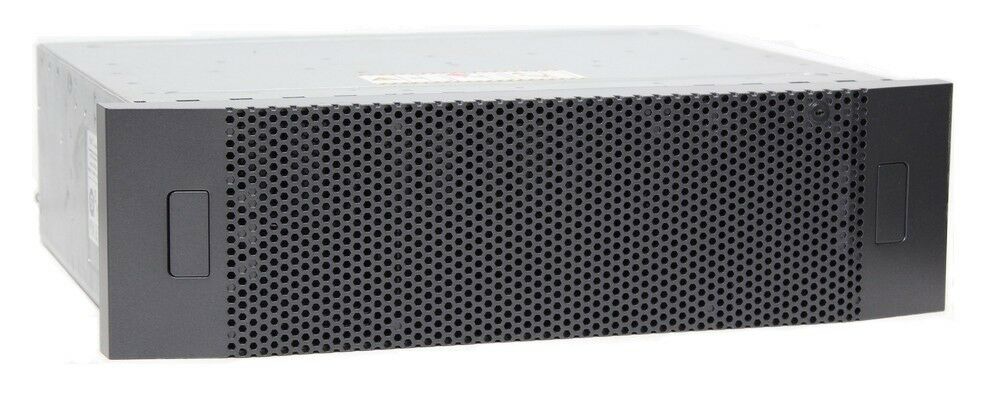
I’m going to setup Fibre Channel storage network to connect ESXi 7 hosts to a TrueNAS Core storage server using a Cisco MDS series switch. I’ve chosen to use Fibre Channel for my VM datastores because of it’s great performance and reliability and the fact that it works so well with VMware ESXi. Fibre Channel will connect the TrueNAS Core storage server (target) and ESXi servers (initiator) over a fabric.
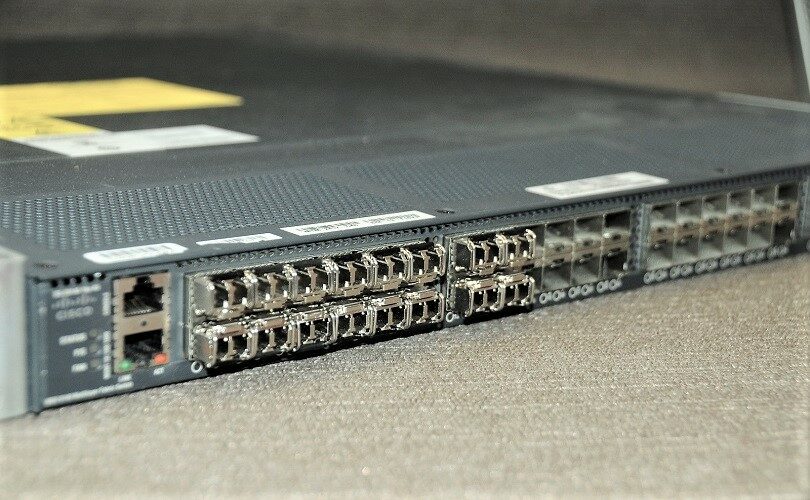
In this setup, I’ve got one Cisco MDS DS-C9148-16p-K9 switch, three Dell R720 ESXi 7 servers and one TrueNAS storage server. All of the servers will have QLogic HBAs with link a speed of 8Gbs. I will create 2 logical networks using VSAN’s to replicate having to separate switches. Although the Cisco MDS 9148-16p-K9 switch has 48 Fibre Channel ports, only 16 of them can acquire port a license by default and the remaining ports have to be activated by purchasing additional licenses from Cisco in 8 port increments.
The Cisco MDS DS-C9148-16p-K9 is EOSL and this make it very cheap to get one on the second hand market. I paid $90.00 AUD for mine. Don’t be concerned that this or any switch has gone EOSL as there is lots left to offer the home user or even business.
You might be asking what EOSL stands for? End of Service Life marks the date on which a device is no longer viewed as serviceable by the manufacturer. After this date, all support services for the product become unavailable, and the product is considered obsolete. Thus Cisco no longer offers any support for the MDS 9148 switches.
Typically, EOSL indicates that the manufacturer is now prioritizing a newer product roll-out and is trying to incentivize system refreshes. Despite being released in 2010, the truth is that your MDS 9148 switch can actually remain productive for many years after EOSL. Most networking gear can function anywhere from 5 – 10+ years past EOSL as long as the equipment is looked after and maintained.
OEMs earn the majority of their profits by selling new technology and not continuing to maintain an asset after the sale. Manufacturers use these strict deadlines as selling points to push their newer, and more lucrative, product lines, all while adding to resource depletion and e-waste. This is known as forced obsolescence.
If you are new to Fibre Channel SAN technology you should take the time to familiarise yourself with the basic terminology in this blog post.
The DC-C9148-16p is very power efficient, drawing under 100W.
1 Power Supply Installed   - 73.5W
2 Power Supplies Installed - 81.2W
Firmware
It’s always a good idea to update the switch’s firmware before deploying them. You can download firmware for the DS-C9148 here, just remember to step the firmware up as recommended in the release notes and always take a backup of the current firmware and you switch config.
Software
  BIOS:      version 1.0.21
  loader:    version N/A
  kickstart: version 6.2(31)
  system:    version 6.2(31)
  BIOS compile time:       01/27/14
  kickstart image file is: bootflash:///m9100-s3ek9-kickstart-mz.6.2.31.bin
  kickstart compile time:  2/24/2020 12:00:00 [02/18/2020 18:48:11]
  system image file is:    bootflash:///m9100-s3ek9-mz.6.2.31.bin
  system compile time:     2/24/2020 12:00:00 [02/18/2020 19:56:46]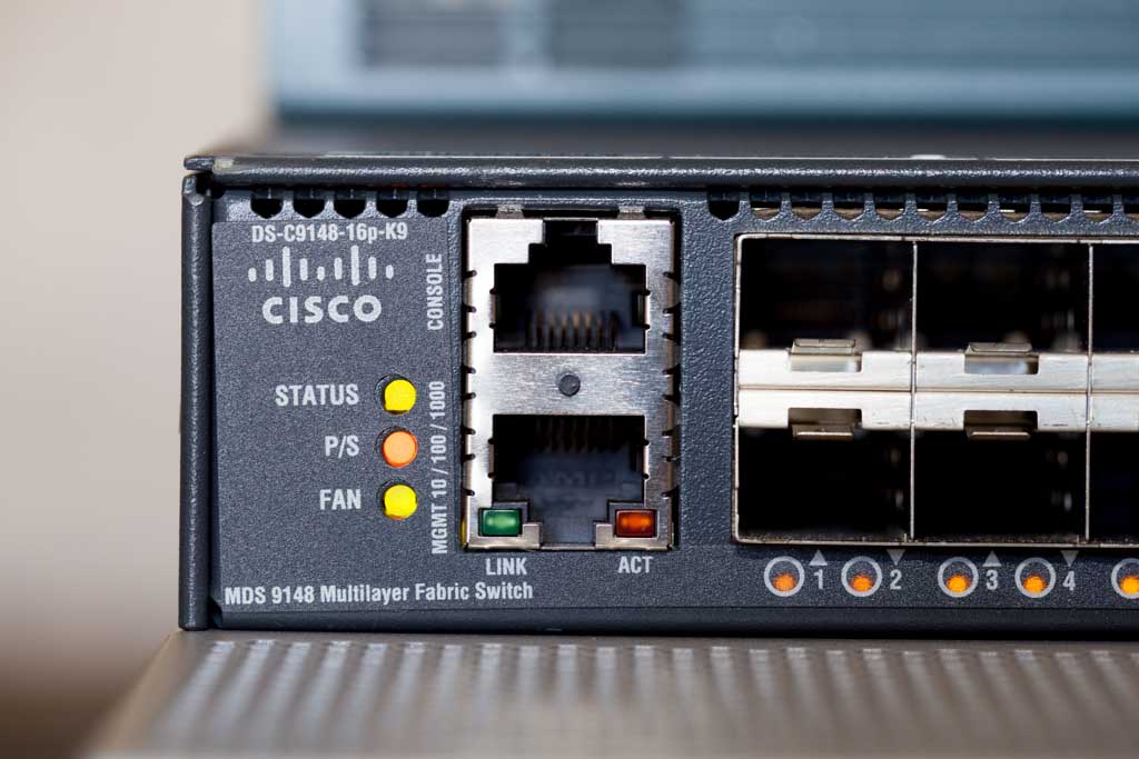
Transceivers and Cabling
For cabling, I’m going to use SR-type SFP transceivers on all of my devices and multi-mode fibre cables for device connectivity. VSAN-A will be cabled in purple sheathed fibre and connect to port one of the HBA’s. VSAN-B will be in aqua sheathed fibre and connect to port two of the HBA’s. This will allow for easy identification of how everything is connected.
I’ll then connect my TrueNAS Core storage server and ESXi 7 hosts to the Cisco MDS DS-C9148-16p-K9 switch as follows:
VSAN-A (Purple)
- FC 1/1: TrueNAS-01 -> PCI Slot 1 -> Port 1
- FC 1/2: TrueNAS-01 -> PCI Slot 1 -> Port 2
- FC 1/3: R720-HOST-01 -> PCI Slot 4 -> Port 1
- FC 1/4: R720-HOST-02 -> PCI Slot 4 -> Port 1
- FC 1/5: R720-HOST-03 -> PCI Slot 4 -> Port 1
VSAN-B (Aqua)
- FC 1/13: TrueNAS-01 -> PCI Slot 7 -> Port 1
- FC 1/14: TrueNAS-01 -> PCI Slot 7 -> Port 2
- FC 1/15: R720-HOST-01 -> PCI Slot 4 -> Port 2
- FC 1/16: R720-HOST-02 -> PCI Slot 4 -> Port 2
- FC 1/17: R720-HOST-02 -> PCI Slot 4 -> Port 2
Cisco MDS DS-C9148-16p-K9 Configuration
Initial Setup
When we’re trying to configure a newly purchased Cisco MDS switch, we can simply utilize the setup utility provided by Cisco. To do so, we need to connect to the device’s console with our laptop and power on the device. Once the switch boots up, it prompts for the admin password and asks if we’d like to run the setup wizard, to which I answer Yes. Then, it asks for some more options, for which we can basically choose default values. You can refer to this Cisco documentation to learn about it.
Switch Config
After the cabling is completed and the initial configuration is done, let’s set up a description for every connected switch port. I will split the switch in half using VSAN’s which will simulate having to separate SAN fabrics but use only 1 switch this way it’s like there are two completely separate SANs with separate switches. I only have 16 port licenses on this switch so I will enable the fist 8 ports on each half of the switch.
SAN-A
SAN-MDS-1# conf t
SAN-MDS-1(config)# interface fc1/1-8
SAN-MDS-1(config-if)# port-license acquire
SAN-MDS-1(config-int)# no shutdown
SAN-B
SAN-MDS-1(config)# interface fc1/25-32
SAN-MDS-1(config-int)# port-license acquire
SAN-MDS-1(config-int)# no shutdown
Name The Ports
I’ll be using Zabbix to monitor the switch so it’s a good idea to give the ports a name so that when you get an alert that something went wrong you will immediately know which device is connected to the port in question.
SAN-MDS-1(config-if)# interface fc1/1
SAN-MDS-1(config-if)# switchport description SAN-A TrueNAS-01-Port-1

SAN-MDS-1(config-if)# interface fc1/2
SAN-MDS-1(config-if)# switchport description SAN-A TrueNAS-01-Port-2

SAN-MDS-1(config-if)# interface fc1/2
SAN-MDS-1(config-if)# switchport description SAN-A R720-HOST-01-Port-1

SAN-MDS-1(config-if)# interface fc1/4
SAN-MDS-1(config-if)# switchport description SAN-A R720-HOST-02-Port-1

SAN-MDS-1(config-if)# interface fc1/5
SAN-MDS-1(config-if)# switchport description SAN-A R720-HOST-03-Port-1

SAN-MDS-1(config-int)# interface fc1/25
SAN-MDS-1(config-int)# switchport description SAN-B TrueNAS-01-Port-1

SAN-MDS-1(config-int)# interface fc1/26
SAN-MDS-1(config-int)# switchport description SAN-B TrueNAS-01-Port-2

SAN-MDS-1(config-int)# interface fc1/27
SAN-MDS-1(config-int)# switchport description SAN-B R720-HOST-01-Port-2

SAN-MDS-1(config-int)# interface fc1/28
SAN-MDS-1(config-int)# switchport description SAN-B R720-HOST-02-Port-2

SAN-MDS-1(config-int)# interface fc1/29
SAN-MDS-1(config-int)# switchport description SAN-B R720-HOST-03-Port-2
SAN-MDS-1(config-int)# exit
Create The VSANs
Lets created VSAN’s with id’s 100 and 200 and included half of my available interfaces into it each VSAN. I also suspended VSAN 1, so that it won’t remain being the default VSAN.
VSAN 100
SAN-MDS-1(config)# vsan database
SAN-MDS-1(config-vsan-database)# vsan 1 suspend
SAN-MDS-1(config-vsan-database)# vsan 100 name SAN-A
SAN-MDS-1(config-vsan-database)# vsan 100 interface fc1/1-8
SAN-MDS-1(config)# system default zone default-zone permit
SAN-MDS-1(config)# system default zone distribute full
SAN-MDS-1(config)# zone mode enhanced vsan 100
VSAN 200
SAN-MDS-1(config)# vsan database
SAN-MDS-1(config-vsan-database)# vsan 200 name SAN-B
SAN-MDS-1(config-vsan-database)# vsan 200 interface fc1/25-32
SAN-MDS-1(config)# system default zone default-zone permit
SAN-MDS-1(config)# system default zone distribute full
SAN-MDS-1(config)# zone mode enhanced vsan 200
Aliases
Aliases allow you to associate pwwn with a name, this will make it much easer to setup zoning when you are dealing with descriptive names instead of a string of characters that make up the pwwn.
Create aliases for VSAN 100
SAN-MDS-1(config)# fcalias name R720-HOST-01-Slot4-Port1 vsan 100
SAN-MDS-1(config-fcalias)# member pwwn 21:00:00:24:ff:37:0a:80

SAN-MDS-1(config)# fcalias name R720-HOST-02-Slot4-Port1 vsan 100
SAN-MDS-1(config-fcalias)# member pwwn

SAN-MDS-1(config)# fcalias name TrueNAS-01-Slot1-Port1 vsan 100
SAN-MDS-1(config-fcalias)# member pwwn 21:00:00:24:ff:0e:b2:da

zone commit vsan 100
Create aliases for VSAN 200
SAN-MDS-1(config)# fcalias name R720-HOST-01-Slot4-Port2 vsan 200
SAN-MDS-1(config-fcalias)# member pwwn 21:00:00:24:ff:37:0a:81

SAN-MDS-1(config)# fcalias name R720-HOST-02-Slot4-Port2 vsan 200
SAN-MDS-1(config-fcalias)# member pwwn

SAN-MDS-1(config)# fcalias name TrueNAS-01-Slot7-Port1 vsan 200
SAN-MDS-1(config-fcalias)# member pwwn 21:00:00:24:ff:0b:78:d5

zone commit vsan 200
Zonning
Now, comes probably the most important task in SAN setup, Zoning. Zoning allows you to control the traffic flowing between the devices, similar to the Access Control Lists in IP network. There are mainly two ways to setup zones in a Cisco MDS: interface based zoning and WWN based zoning. When interface based zoning is used, only the member interfaces can communicate with each other. So, if the devices are connected on different ports of switch, the zoning might not work correctly. Whereas with WWN based zones, devices can only communicate with other devices with member PWWNs. Thus, it works correctly even when ports are changed, but doesn’t work if the ports or HBA cards on server or storage are changed. I’m going to use PWWN based zoning.
I need to create zones to allow communication between each server and the storage array . That way these servers will have their own separate communication path to the storage array and won’t be access each other.
VSAN 100
SAN-MDS-1(config)#zone name R720-HOST-01-TrueNAS-01 vsan 100
SAN-MDS-1(config-zone)# member fcalias R720-HOST-01-Slot4-Port1
SAN-MDS-1(config-zone)# member fcalias TrueNAS-01-Slot1-Port1

SAN-MDS-1(config)# zone name R720-HOST-02-TrueNAS-01 vsan 100
SAN-MDS-1(config-zone)# member fcalias R720-HOST-02-Slot4-Port1
SAN-MDS-1(config-zone)# member fcalias TrueNAS-01-Slot1-Port1

SAN-MDS-1(config-zoneset)# zone commit vsan 100
VSAN 200
SAN-MDS-1(config)# zone name R720-HOST-01-TrueNAS-01 vsan 200
SAN-MDS-1(config-zone)# member fcalias R720-HOST-01-Slot4-Port2
SAN-MDS-1(config-zone)# member fcalias TrueNAS-01-Slot7-Port1

SAN-MDS-1(config)# zone name R720-HOST-02-TrueNAS-01 vsan 200
SAN-MDS-1(config-zone)# member fcalias R720-HOST-02-Slot4-Port2
SAN-MDS-1(config-zone)# member fcalias TrueNAS-01-Slot7-Port1

SAN-MDS-1(config-zoneset)# zone commit vsan 200
Finally, I need to create two zone sets with one for VSAN 100 and the other VSAN 200 containing the zones created above and activate them.
VSAN 100
SAN-MDS-1(config)# zoneset name Zoneset_1-V100 vsan 100
SAN-MDS-1(config-zoneset)# member R720-HOST-01-TrueNAS-01
SAN-MDS-1(config-zoneset)# member R720-HOST-02-TrueNAS-01

SAN-MDS-1(config-zoneset)# zone commit vsan 100

SAN-MDS-1(config)# zoneset activate name Zoneset_1-V100 vsan 100
SAN-MDS-1(config)# zone commit vsan 100
VSAN 200
SAN-MDS-1(config)# zoneset name Zoneset_1-V200 vsan 200
SAN-MDS-1(config-zoneset)# member R720-HOST-01-TrueNAS-01
SAN-MDS-1(config-zoneset)# member R720-HOST-02-TrueNAS-01

SAN-MDS-1(config-zoneset)# zone commit vsan 200

SAN-MDS-1(config)# zoneset activate name Zoneset_1-V200 vsan 200
SAN-MDS-1(config)# zone commit vsan 200
Enable NPIV
N port identifier virtualization (NPIV) provides a means to assign multiple FC IDs to a single N port, and allows multiple applications on the N port to use different identifiers. NPIV also allows access control, zoning, and port security to be implemented at the application level. This is important in an environment with a mix of Windows systems, virtual machines and boot from SAN in order to prevent automatic or accidental reformatting of targets containing unrecognised file systems. To turn on switch wide NPIV run the below command.
SAN-MDS-1(config)# feature npiv
Now make sure you save the running config to the start-up config or all settings will be lost on a switch reboot.
SAN-MDS-1(config)# copy running-config startup-config
[########################################] 100%
Copy complete.
Note.
Any time you make changes you will have to run the below commands to make the changes active. Always make changes to one fabric at a time, e.g. make changes to SAN-A and validate that all servers can still communicate with the storage that they are supposed to be able to communicate with. This way if you make an error in config only SAN-A is impacted and SAN-B will continue to support the connected servers.
You need to commit the zone changes to the VSAN and then enable the changes for the same VSAN, also don’t forget to save the running config to the startup config.
SAN-MDS-1(config-zoneset)# zone commit vsan 100
SAN-MDS-1(config)# zoneset activate name Zoneset_1-V100 vsan 100
SAN-MDS-1(config)# copy running-config startup-config
I recommend that you chack your settings have been pushed to the active zoneset with the below command. You should always check that you changes are active and the no adverse changes have happened on SAN A before making any changes on the other SAN B.
SAN-MDS-1(config)# show zoneset active vsan 100
zoneset name Zoneset_1-V100 vsan 100
  zone name R720-HOST-01-TrueNAS-01 vsan 100
  * fcid 0xb00100 [pwwn 21:00:00:24:ff:37:0a:80]
  * fcid 0xb00600 [pwwn 21:00:00:24:ff:34:9c:c2]
  * fcid 0xb00700 [pwwn 21:00:00:24:ff:34:9c:c3]

  zone name R720-HOST-02-TrueNAS-01 vsan 100
  * fcid 0xb00400 [pwwn 21:00:00:24:ff:90:28:22]
  * fcid 0xb00600 [pwwn 21:00:00:24:ff:34:9c:c2]
  * fcid 0xb00700 [pwwn 21:00:00:24:ff:34:9c:c3]

  zone name $default_zone$ vsan 100
SAN-MDS-1(config)# show zoneset active vsan 200
zoneset name Zoneset_1-V200 vsan 200
  zone name R720-HOST-01-TrueNAS-01 vsan 200
  * fcid 0x080000 [pwwn 21:00:00:24:ff:37:0a:81]
  * fcid 0x080600 [pwwn 21:00:00:24:ff:34:c0:c4]
  * fcid 0x080700 [pwwn 21:00:00:24:ff:34:c0:c5]

  zone name R720-HOST-02-TrueNAS-01 vsan 200
  * fcid 0x080300 [pwwn 21:00:00:24:ff:90:28:23]
  * fcid 0x080600 [pwwn 21:00:00:24:ff:34:c0:c4]
  * fcid 0x080700 [pwwn 21:00:00:24:ff:34:c0:c5]

  zone name R720-HOST-01-TrueNAS-02 vsan 200
  * fcid 0x080000 [pwwn 21:00:00:24:ff:37:0a:81]
    pwwn 22:00:00:24:ff:6a:7f:38

  zone name $default_zone$ vsan 200